
The goal of this project was to learn how to use chaos to control mixing in gases. Specifically, we used tiny flaps mounted in the nozzle of an air jet to selectively enhance or suppress instabilities in the flow. The engineering objective was to control chaotic mixing in this jet, with an eye towards fuel injector design, drag reduction, etc. All control strategies require some kind of model, of course, and modeling a laboratory free shear flow is not an easy task; we used point-vortex models and data assimilation to solve this problem.
The basic idea is to co-opt the instability of the flow. A small disturbance, in exactly the right spot, can generate or suppress large-scale turbulent fluid motion: the classic "sensitive dependence on initial conditions." The "right spot," for the purposes of the air jet, is the boundary layer at the edge of the flow. Given the length scales and Reynolds numbers that are involved, the microelectromechanical systems (MEMS) process is exactly the right technology with which to build actuators for this purpose. MEMS are integrated microdevices that combine electrical and mechanical components and thus allow sensing, actuating, and processing capabilities to be distributed widely in space. For instance, arrays of micro-flaps, several hundred microns high, each with a small associated processing element, can be reliably manufactured on a single chip.
Our experimental apparatus consists of a planar air jet and a set of MEMS actuators that can be used to selectively perturb the boundary layer of its flow field. Here is a schematic and a photograph of the jet:
|
|
Compressed air is squirted into the bottom of the jet via a collection of hoses, five of which are visible in the images above. The air flows vertically through a plenum (the aluminumtower sections) and a contraction (the black piece on top) and emerges through a rectangular slit with dimensions of {2.50 +/- 0.01mm} by 400mm, giving an aspect ratio of 160:1. This slit-shaped nozzle is shown in closeup below.
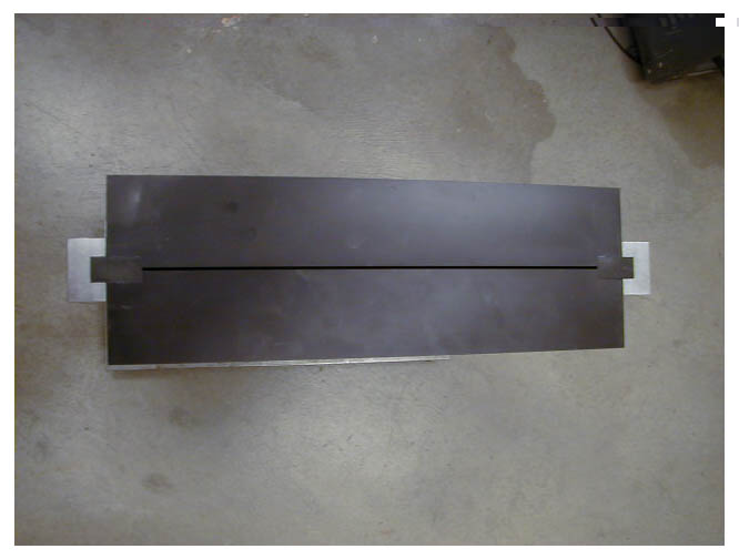
The plenum contains a variety of flow-conditioning devices that serve to reduce the turbulent intensity in the flow; the contraction is designed to further suppress turbulence and reduce non-uniformities in the velocity profile. Because the resulting jet is so long, the flow field may be considered two-dimensional across its central cross-section; because it is so narrow, the entire jet is really a "boundary layer." This geometry was chosen to make the problem amenable to simultaneous analytical, numerical, and experimental exploration. The three-way corroborative nature of this approach - which is critical to any formal, extensible control scheme - makes it unique in the MEMS/flow control literature.
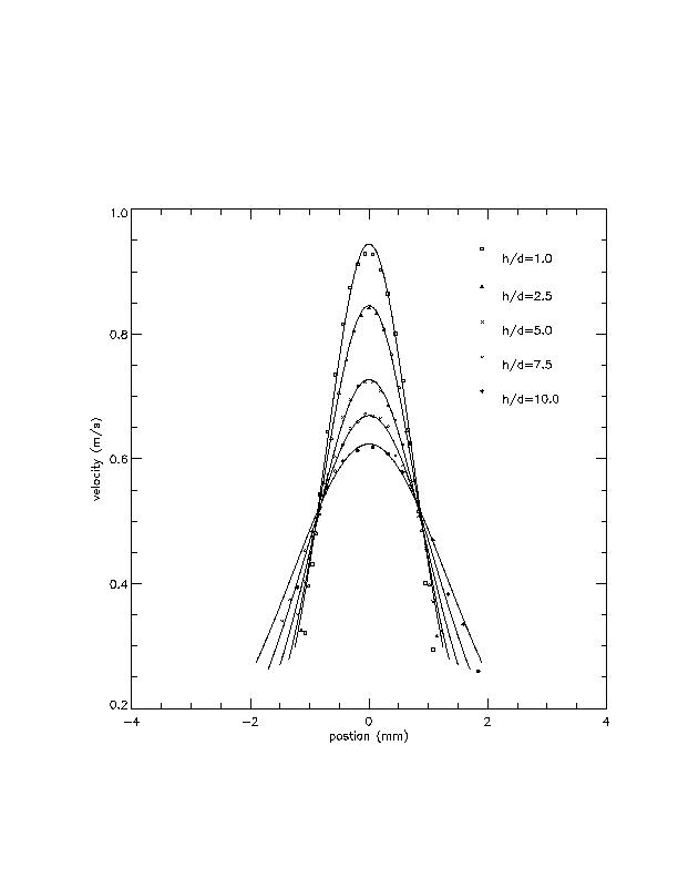
Most of our experiments have used flow rates of several meters per second, so the Reynolds numbers are quite low (10-300). This is limited only by the compressed air supply, not the apparatus, and we plan to explore higher Re flows as well. Using a hotwire anemometer suspended in the flow, as shown below, we have characterized the flow, measuring the velocities at different points in the jet:
 |
 |
The results show that the flow is fully developed in and near the nozzle:
 |
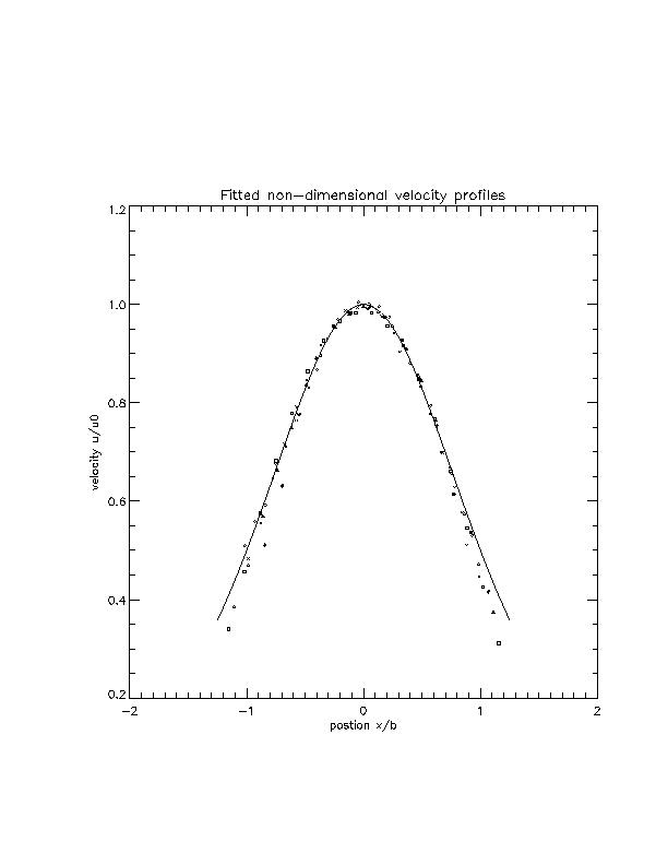 |
There is actually a small oscillation in the velocity, as you can see from this time-series image from the hotwire anemometer:
 |
Here, we are plotting the fluctuations of the downstream velocity about its mean. The hotwire was situated about 0.5mm off the jet centerline, which is where these fluctuations are largest. This 16.83Hz oscillation is one of the lowest order unstable modes, which is being excited intermittently by room air currents. Its amplitude varies, and is very small.
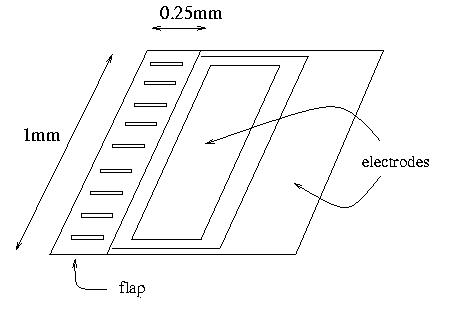
The MEMS actuators that we use to perturb this flow are 1mm by 0.25mm flaps. They consist of two layers of material with different resistances, and they move via the bimetallic effect; an applied voltage causes the layers to heat (and thus deform) at different rates, so they bend. This is visible at the left side of the color image below:
 |
 |
 |
The flaps are mounted on 75um high solder "spacers" using the flip-chip solder bonding/alignment process developed by Y. C. Lee. The flaps are not completely rigid, so they bow down a bit in the middle. Our later designs include a set of joist-like structures to stiffen the flap and prevent this. The tip deflection is roughly linear in the applied voltage up to a maximum of about 25 microns. The resonant frequency is about 20Hz; the flaps can be driven much faster, but the tip deflection decreases with increasing frequency. The plots below show these two effects in action:
 |
 |
Many of the fundamental instabilities of a flow are born in its boundary layer: the region where the flow velocity is changing rapidly. The intuition behind our control strategy is that the boundary layer is the most sensitive part of the flow - and is therefore a good place to put an actuator. For this reason, we mount our flaps along the edge of the nozzle, so their bending action expels a small puff of air into the side of the jet, which perturbs the velocity. (The thermocouple effect that controls the bending also plays a role here, via the heating of the flap and the resulting buoyancy forces.)
 |
By manipulating these flaps (e.g., in phase, antiphase, etc.), we have been able to excite both of the fundamental instabilities (symmetric and antisymmetric) across a wide range of frequencies. If we force the flow (on one side only, for now) by moving the MEMS flaps in a sinusoidal up/down pattern at the natural frequency of 16.83Hz, for instance, the flow velocity clearly demonstrates that the corresponding antisymmetric instability has been excited:
 |
Note the difference in the vertical scales of the two time-series signals, and the regular nature of the oscillation in the latter, as compared to the nonstationary signal in the previous time-series image. Below are the frequency spectra of the two signals, which make the difference more obvious (left is unforced and right is forced). Again, note the vertical scales on the two plots:
 |
 |
These photographs show what this looks like to the eye:
 |
 |
The jet responds equally well to other forcing frequencies; below are spectra for a few other examples (5Hz on the left and 50Hz on the right):
 |
 |
The range of frequencies that it is possible to excite is a complicated function of Re, geometry, etc.
One promising application of these ideas and techniques is the design of combustion chambers. Fuel injection systems, whose purpose is to mix fuel and air uniformly, are designed in an almost purely experimental fashion. While designs that emerge from such a procedure may perform very well, they are also highly specific: one cannot typically generalize from their properties to solve another fuel injector design problem. Moreover, a system designed for one set of conditions (e.g., 55mph) is not necessarily optimal for a different situation (e.g., I-90 in Montana on a warm, dry day). The knowledge that we gain from this research project will hopefully not only let us design chambers that can adapt for optimum mixing under different conditions, but also help us understand some of the general principles behind combustion chamber design.
This is a difficult project, and it calls upon advanced techniques from several different fields:
Control strategies require models, but numerical models for predicting fluid flows and other complex systems have heavy computational demands and cannot track unmodelled effects like perturbation or drift. Meteorologists often address this tracking problem by "assimilating" data into their numerical models to keep them on track. We use this technology to model our jet, correcting a 2D point-vortex model with positions and strengths of the actual vortices in the jet, extracted from the PIV data shown above.
Exploring data assimilation in a laboratory setting is interesting & important for two reasons. First, while simulated experiments with well-characterized noise---the "perfect-model experiments" that are common in the data-assimilation literature---are very useful, real-world effects like drift almost invariably violate one's expectations and intuitions. Since the task of data assimilation is to help solvers track these kinds of effects, understanding them---not uncertain simulations of them---is critical. Second, in our controlled environment, we can isolate, explore, and replicate physical and numerical effects. Any model could, potentially, be corrected with data in order to compensate for its inherent approximations, but doing this requires a thorough understanding of how different solvers react to dynamic data injection.
See the papers listed below for more details on these points.
People:
 Tom Peacock and Liz Bradley
Support:
Papers and abstracts:
Links:

Copyright 2000, Elizabeth Bradley and Thomas Peacock.
All rights reserved. Many of these images appear in other publications and may not be reproduced without appropriate citation.