Yesterday, during lecture, I intended to work my way through an example of the iterative process of analysis and design that I discussed while closing out the slides for Lecture 5. I got distracted with having to switch over to the slides for Lecture 6 and completely forgot about the example. My apologies.
So, now I will present the example here and then you should be ready for Homework 3, which will be appearing on the class website soon.
Note: This example comes from the excellent book Head First Object-Oriented Analysis & Design that I've used for the past couple of years as the textbook for this class. If you are interested in software engineering and object-oriented analysis and design, I encourage you to obtain a copy of the book.
During Lecture 5, we looked at this example set of requirements.
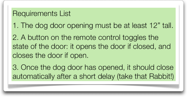
These requirements represent the start of a conversation with a customer that would like us to build software to control an automated dog door. The dog door can be opened and closed via a remote control and it features a "bark recognizer" that allows a pet to be automatically recognized via its bark and will then open the door on behalf of the owner. Finally, the door needs to automatically close after a short delay to protect against the owners forgetting to close the door themselves.
These requirements led to the following use case which we discussed during lecture 5.
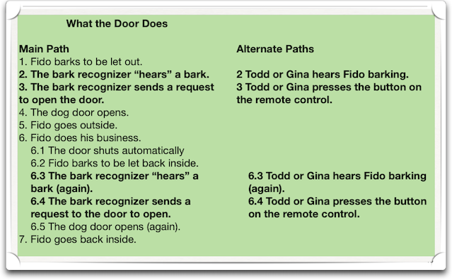
It displays all of the possible paths for handling the situation in which a dog is inside the house, needs to go outside for a moment and then returns back inside the house. Since the goal of the actor (the dog) is to return inside at the end of the use case, the use case does whatever it can to acheive this goal no matter what goes wrong.
To get a better sense of all the conditional paths, we can convert the use case into an activity diagram. Here's the activity diagram that I created... note that I didn't shoot for an exact one-to-one correspondence. I just captured the essence of the use case in the paths of the activity diagram.
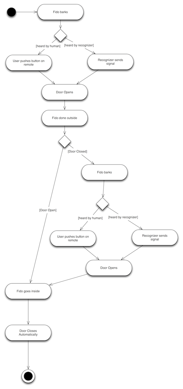
(Note: A more legible version of this diagram is available on the Sample Code page for download.)
It is clear that one important object in this system is the dog door itself. We can create a state diagram that shows the essence of its behavior.
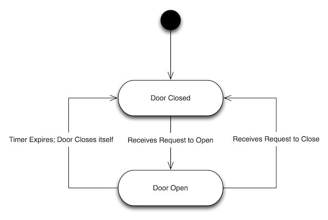
The door is either open or closed and all it does it transition between these states. It is always explicitly told to open but it can be told to close in one of two ways. As a result, we show that there are two ways to get back to the closed state from the opened state.
Note: We've already seen a sequence diagram for this use case on slide 48 of Lecture 3. This sequence diagram spans multiple activites contained in the activity diagram and shows the scenario in which the bark recognizer hears Fido, lets him out, Fido gets stuck outside and the recognizer once again hears him and lets him in. Note: that a sequence diagram always shows just ONE path through a use case or activity diagram. There are no conditional constructs in the notation for sequence diagrams. If you wanted to show a different path through the activity diagram, you would need to create a separate sequence diagram. Note also: The sequence diagram here spanned multiple activities because the individual activities of our activity diagram were fairly simple. You will sometimes have a very complex activity contained in an activity diagram and then it might be the case that you create a single sequence diagram just for that activity and then use another sequence diagram that shows how objects are interacting in the other parts of that activity diagram.
The final piece of the puzze then is a class diagram. Based on all the information we have so far (don't forget to take a look at the sequence diagram!), we could construct a class diagram that looks like this:
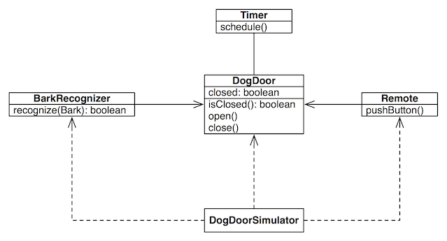
Here we have classes that were drawn from the requirements, the text of the use case, the sequence diagram and the state diagram. With a little thought, we can see that the scenarios described in the use case and represented in the activity diagram can be supported by the classes here. Note: we included the Remote class because we knew of its existence from the requirements and the text of the use case. It wasn't actually used in the sequence diagram that we created but that's okay. Different sequence diagrams will represent different paths through the use case and one will eventually be created that shows how the remote control is used.
Once you reach this point, you have completed most of the work of processing a single use case. To move further in your analysis, you could pick another path through the current use case and create another sequence diagram to see if it provides additional insight into the domain. Or, you could select another use case (creating it if needed) and begin again.
Eventually, you'll reach the point where all use cases have been created and elaborated and you're ready to move on to add detail to your diagrams with the goal of transitioning into the implementation phase.
How will you know when you've created all the use cases that you need to address? When you and your client can no longer think of additional tasks for the types of users (end user, administrator, affiliate, content provider, etc.) you've identified. In my experience, this process lets you converge on a “good enough for now” sense of completness pretty quickly and then you can get on to the fun of coding things up!