|
|
|
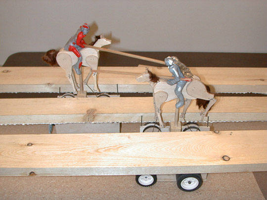
The Joust! is a fanciful throwback to medieval times when knights would hone their skills or settle scores with a little sport involving lances, horses, flailing limbs, and sore sides. True to its name, this automaton project featured two horse-mounted knights, with each horse on a cart independently controlled by a cricket. Each horse was mounted on a moving cart, and each of the four wheels at the top of the chart are connected to a [very well contoured] leg, resulting in a natural gait supplied by the friction between these wheels and a suitable surface as the cart moves. Rather than have a single cricket controlling the action, the two crickets communicated with each other via infrared much like a human conversation: each had some idea of its location relative to the other, as well as whether it had passed the other, or had reached home position. The in-class demo showed off the strength in this thinking: each knight had occasional false starts, blind spots and a randomness to them that gave a life to the project much more than clever programming ever could.
The two components that define the knight's joust are the horse carts and the stage. Both play a pivotal role in the mechanics of the joust. The cart is driven forward on a set of four wheels. At the top of the cart there are four discs that rotate freely. Those disks are then attached via wires to a corresponding horse leg. The horse legs are in-turn connected to the horse's body and the body is supported by a dowel running back down to the bottom of the cart. It's a very simple cart and has a nice looking horse at the top but what makes the horse move. Well, that's where the stage comes in. The cart rides under the stage with the horse above and the wires & dowel going through a slit in the stage. The discs then are against the bottom of the stage and when the cart moves, the disks turn. This turning motion results in the off centered wire to thus move up/down and forward/backward making the horse leg move.
This design was originally thought of in our first few meetings in class. It evolved from a horse with wheels attached to its legs on a bumpy course, to a cart with wheels below the stage that turned the wheels at the appropriate time, to a cart with discs that were in constant contact with the stage. We worked out many of our design problems early with a LEGO prototype. This prototype showed us that the length of the wires and the height of the horse were a large factor in the correct leg movement. Another factor that the prototype exposed was the leg joints of the horse. The shoulders needed to be very loose while the knees had to be fairly tight to accomplish the upward motion of each leg. Also the fact that the horses body had to be very solid otherwise the alternating upward and downward motion of the legs would twist and turn the horse in many unnatural ways. All of these factors were weighed into our design and followed us until the last moments of construction.
The horse itself is a wonderful set of movements. The entire horse is cut from Ľ" basswood, by hand with a jigsaw. The torso is made up of four pieces, two that are the complete body including the head, and two on the outside that are just the lower body to outline the shoulder structure. The front and back legs are in two sections, the upper and lower. The front pair is much smaller than the back and bend forward as opposed to backward. The upper sections of leg needed to be attached to the horse in a loose fashion. While were looked at brass and other metal wires as pivots, we found that nylon thread was the strongest, loosest, most realistic and invisible connecting material. Thus the upper legs were attached from side to side of the horse with two drilled wholes for each leg (Eric's Boy Scout knot tying skills were very useful). For the joint to the lower legs each upper leg was formed to make a 2D socket were the lower leg would fit into. Each one of the lower sections was notched at the back of their pivoting ball so as to force the leg to pivot in the intended direction (forward for the fore and backward for the rear) when an upward force was applied. The joints were tied together using a whole in the upper and lower sections, which were tied together with metal wire acquired from a set of paper clips. The joints themselves looked great in that the notch actually looked similar to the set of tendons that are in that section of a horse's leg.
The final touches of contour were added with a grinder on a Dremill™, adding the extra detail of muscular structure. The ears of each horse were painstakingly ground out of a section of dowel and then attached! Tail and mane were trimmings of doll hair strategically trimmed and then glued to each horse. We knew that the horses themselves were a going to be the most focused on feature of the project. We also noticed that they were almost dolls in themselves at the point we had each of them standing alone on their dowel attaching the ears and combing the hair. When finished, we had a horse that was very realistic and had gorgeous leg movement.
Determining how the cart was going to work was an on going debate in the team. We ended up returning to our original design after failed attempts at moving the wheels above the stage and between the legs and then to corners of a thin cart that lay between the legs. All of these became difficult to implement and were limited in how we could construct them with our materials and tools. The final design was a slender cart with one driven wheel (the three others were free) the discs at the top slightly higher than the two side walls, and a dowel up the center for the horse. Once we finished one we replicated it for the opposing horse.
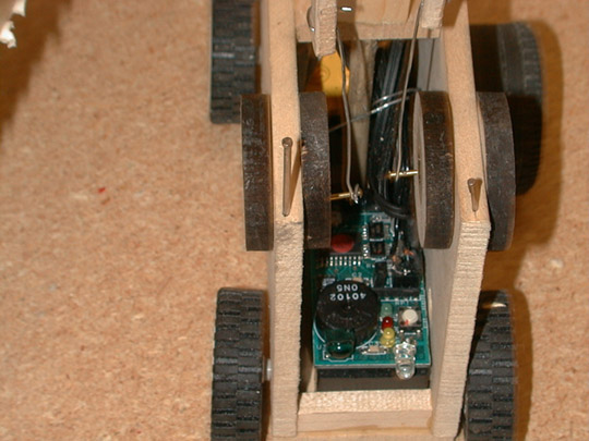
Each of the 8 discs on the cart was cut from the same basswood as the horse instead this time using a laser cutter. For each leg two discs were attached to either end of 1/2" long dowel that went through the cart. Thus the discs could rotate freely while still being solidly attached to their pivot and with two disks we would have more contact with the stage and assure us leg motion from the bottom of the stage. The sides and the bottom of the cart were again from basswood simply glued together with strategic supports from side to side and with boxes to hold the motor for one wheel, and the cricket in the front of the cart.
The LEGO motor, once in its box in the cart, poked through the side to attach to a rubber wheel. The other three rubber wheels were simply attached with on LEGO loose joint to a drilled whole in the sidewall. At the very top and center of the cart there was a side-to-side support with a whole in it to stick the horses dowel.
The cart actually was much simpler than the horse in construction and in detail seeing as how it would be below the stage and not seen by the masses. A few points of tweaking had to be made during construction: the wheels could only be attached so low and the tire could only be so wide that we were forced to use tires that were barely tall enough to keep the bottom of the cart from dragging against the floor of the stage. In addition the driving wheels were not solid instead they were air filled, which lead to drooping when pressure was applied to the top of the cart. A bit of tissue paper stuffed inside the tires made them perfectly rigid and allowed the extra clearance we needed.
The source of the driving wheels power to make the whole horse and cart move lay in our motor, which was controlled by the cricket. We considered several ways to control the motors: either have wires that led to each cart, or fiber optics between each cart to allow un-interrupted communication between two crickets. We found that we could use two isolated crickets to our advantage.
We found that the crickets IR transmitter/receivers were able to reliably communicate at the distance we needed them to, and with the right programming we could actually have each horse determine when it had passed the other by keeping track of the ability to communicate with the other cart. Thus when the two carts passed and the actual lance hit had occurred the crickets wouldn't be able to communicate and thus they would know they have passed. Using this we found that using a set of states to determine how the motor should be turned on and in what direction would work well.
The states were: waiting for the other horse to say ready, running toward the other horse while communicating with it, having lost communications backing up until it hits the wall. Simple enough a loop would accomplish that task. Instead we found that the small inaccuracies could hurt us and the way we determined how we had lost communications was paramount. The communications during running was solved by having one horse start by sending a token. He would continue sending that token until he saw that the other horse had received that token and incremented it by one. In this manner the two horses would trade the token back and forth until they pass. At that point they would not see that incremented token for a certain timeout and they would know they lost communications and to go into the backup state. This worked very well except for one factor, that they had to allow for enough time to account for simple timing issues (they were both sending at the same time so neither saw what the other was saying). This fairly long timeout did work and was the deciding factor but what helped was a form of "follow the leader". Thus if during the forward motion a horse saw that the other cart was backing up then it new that the other thought they pasted and it was time to back up no matter if the timeout had occurred. This worked great and was the final running mode.
The other states were pretty simple. Backup until a touch sensor says you have hit a wall, then get ready for the next joust. The "I'm ready" state was simple but interesting as well. The horse waited for 30 seconds for the jousters to be re-positioned on the horse then it was time to run. Though the horse had to start at the same time otherwise one had an advantage. Thus they had another simple form of communication, they said back and forth to each other: "Ready, Set, Go". Amazingly simple but it worked, and the fact that they relied on communication to continue moving forward we got a very interesting side effect, the false start.
The horses actually have a false start. This occurred when one horse saw the "GO" but the other didn't. The one that heard "GO" starts running while the other sits and waits. The one that is running never gets its token from the other and eventually times out (split seconds) and thus goes into the backup state, and it starts all over again. This little side effect made for a very lifelike and interestedly random enough game to keep its spectators interested for a very long time.
The bane of our existence was the stage. All of our carefully orchestrated movement, highly refined carts, and interesting programming to control the motor all relied on the stage applying just enough pressure on the discs to move the legs, but not to much so as to keep the cart from moving. We came up with a very well thought out design. We made the base out of particleboard and the sides out of planks of wood. Then the top of the stage was created. It consisted of three planks that would supply the force to the discs moving the legs and hide the mechanism from below. These planks were on a side support that sat on the sideboards. Attached to the lower section with a dowel on each end. Thus the stage/planks could be raised and lower using wedges or spacers to keep just the right amount of friction on the discs to keep the legs moving with out overpowering the motors. This was great and allowed it to be moved and just retuned, also it would last for years, if the discs wore down you could just tune it a bit. The problem that we didn't predict was how warped the planks would be. They had such a large crown in them that on the ends that they were so tight the carts wouldn't budge, but in the middle the discs didn't even touch and thus the legs hung limp. All said and done, to get the gorgeous movement of the legs we needed new FLAT planks.
One other interesting tweak we came up with during creation of the stage was to fix a bug. The problem was that the touch sensors weren't being fully depressed because when they hit the wall the wheel would just slightly come off the ground and not be able to drive them all the way against the wall, and they would just sit there trying to backup. We resolved this with a bit of sandpaper placed just under the driving tire, right next to the wall. This allowed the tire to raise a bit still but gave it enough friction that it could push the cart back and thus press the touch sensor.
The most educational and entertaining piece of this project is the jouster himself. With a little bit of clay and a dowel the users of this educational toy could create different types of jousters to determine which combination of attributes were best for hitting the other jouster hard, or staying on the horse, or even all around quality. Eric spent a good amount of time sculpting beautiful jousters that exhibited different qualities. The evil knight (gray & red) was very massive and could hit hard, but also had a very high center of gravity and thus was easy to knock off. On the other hand the good knight (gray & white) had a low center of gravity with a very large butt, which allowed him to stay on the horse well. Just the hundreds of different combinations of weight placement and cross-sectional area manipulations could keep the average players entertained and allow them to realize a bit of physics that could later turn into simple intuition.
Our automaton combines aspects of a horse-racing toy with the animated animal movements present in many of the exhibits at the Cabaret Mechanical Theater, but adds an element of surprise due its random and unpredictable nature. The joust does not lend itself well to a "walk-up and use" environment. We did not incorporate any user controls or labels, but the intent of the automaton was obvious. If we had more time we may have focused on designed a cricket-based remote control to begin, delay, or cancel the joust. Secondly, a simple icon based description what to expect and how to place the riders would have been in order. The presentation of the toy could have benefited from more detail. We would have liked to create a color backdrop display of a king and spectators, with trees, mountains, and a castle in the background. The surface could have been made to look grassed with trails underneath the horses. The mechanism itself is not completely visible to the user. The rods extending from the interior cart cams to the each hoof are visible, but the driving cams and cart enclosure are hidden by the surface. The logic and directional motion control of the horses is encoded on the cricket and is naturally hidden from the user, as well as the infrared communication method.
The automaton was successful at creating the entertainment value we intended. Not knowing just how the joust will end can be very compelling for an audience or even an individual user. The clay allows for another dimension of surprise by reacting in limitless ways to damage from the lance and from the ground. Our automaton was not intended to be educational or have any purpose other short of entertainment. The fun factor is present and is immediately apparent by the response of "oohs" and "ahhs" from the audience as a clay rider is forced from his mount.
From the very start, this automaton (referring to the two horse carts, the knights and crickets as one lump sum) was intended to be self-running and entertaining. If there are any educational benefits to be gleaned from this project, it is more from the various design decisions we made along the way, rather than intentional efforts at: "Here kids, this is how jousting works."
One such design decision, proving again that the whole is often more than just the sum of parts, was to have independent knight/horse/cart combinations (henceforth called knorct(s), just for fun . The educational benefit of this has effects that reach beyond the building of mere automata. We've been mildly interested in the design of artificial intelligence, and the elegant programming solution to the problem of getting two crickets to "know" each other worked mostly because they were independent. In other words, those simple two crickets displayed more intelligence (between them) than several intensive AI attempts around. This complexity-from-simplicity must have educational value for others wandering along this path.
One thing students absolutely detest about studying mechanics, is the tendency of textbooks and teachers to ignore friction. They argue for mathematical simplicity, unfortunately, that comes at the cost of little understanding: even in space (albeit with a very low density of hydrogen), there is a bit of friction. Building this project was a good lesson in the different forces that came to bear on the various parts of the knorct. Using this to teach students about static and kinetic friction as they tested this and tried that would really help to gain a better appreciation and understanding of this physical world.
As mentioned during the presentation, a less intensive educational lesson can be obtained by exercises in molding different types of riders (made of putty): experimenting with centers of gravity, and strategic positions of rider on horse. We certainly had tons of fun with the knorcts the night before the demonstration in this manner.