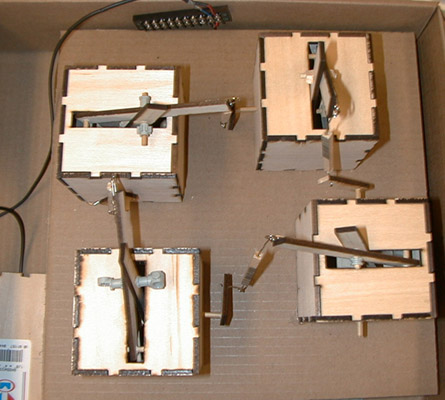
The Crank project consists of four identical boxes, each with a crank on one side, and each with an arm protruding from a slot in the top. They are arranged in a square in such a fashion that each box's arm is attached to the next box's crank. In this way, each box turns the crank of its neighbor. If we had been able to completely realize our vision, the four boxes would sit on a turntable atop a larger box with a hand-crank. As the user turns the hand-crank, the turntable would begin rotating. A rotation sensor attached to the turntable would, using a cricket, start a motor attached to one of the small boxes, which would begin turning its crank. Therefore the smaller boxes would turn at a rate determined by the speed of the turntable, which is ultimately determined by the user.
The bulk of our project was built out of 1/8-inch basswood. When we first started designing our project, we built an initial prototype out of Lego. This prototype consisted of one of the four boxes and had a moving arm and crank. When working with the Lego prototype, we found that the fixed size of Lego would not work for us. We needed to be precise in how things fit together and in our measurements. This is not possible with Lego, as they have fixed lengths and fixed distances between the different holes in Lego blocks. This forced us to seek other alternatives. Since our class has access to a laser cutter, we thought that it would be easiest to use a material that could be easily cut with the laser cutter. Many of the examples of what the laser cutter could do were done in wood. This led our team to take the route of the 1/8-inch basswood. It is a fairly sturdy wood and has a fine grain to it, making it look nice.
Once our group decided on what material we would be using, we had to start designing the different pieces we would need. The main structure of our project is four cubes. Therefore we knew that we would need to make 6 sides for each cube. We later realized that two of these sides would need holes in the center for the shaft that would drive the internal mechanism. We also would need a slot in the top of the cube for the arm to stick out of. The next pieces we needed to design were the cams. We needed two cams for each cube. We did not know exactly what diameter cams we would need at this point. The diameter and offset of the holes in the cams would define the amplitude of the arm. To make our lives a little easier, we chose a 1.5-inch diameter to start with. We could then use these cams to make measurements for the final product. We needed to do the same type of procedure for the arms as well. We knew that we needed three different parts for the arms, but we did not know exactly how long the needed to be or where to make the holes in the joining parts to make it work correctly. Again, we choose an arbitrary length of four inches and would go from there. After defining all of the measurements on paper, we then had to turn these conceptual drawings into code that the laser cutter could understand. After a short lesson in HPGL code, we quickly had a few files defining our shapes to be cut out by the laser. Once we had our cut pieces, it was back to the workbench to start building.
This building stage marked the beginning of our second prototype. We now had enough cut wood to make one full box, and a few other pieces to make just the joining side of the second box. This was all we needed to tell if our project was feasible. We began to build the first box and realized a few different problems. First, we realized that the laser cutter, although precise in measurements, was not so precise in how the laser beam spread. The holes we had the laser cut out for us we a little larger than expected. As a result, the shafts that went through these holes were not stable at all. They wobbled and had a lot of play in the way they moved. This was one thing that we noted as something that needed to be fixed for next time. We also noted that it took too long to put the sides of the walls together and would need a different design for them. Another related issue arose from the shafts we were using at this time as well. We needed some way to keep the shafts in place. Therefore, we had to cut many little wooden washers to help keep them in place. This was something we found we need a mass quantity of. After we got around these issues, we moved on to putting the whole box together and attaching it to the side of the next box. At this point, we had to take a time out and figure out how to make a joint that had two degrees of freedom to move side-to-side and back-and-forth. At the point of this prototype, we came up with a Lego piece that was basically a ball joint. This gave the joint enough freedom to move like it wanted to. This was important because we needed to turn an "up and down" motion into a circular motion. Without this movement, our project would not work at all.
At this point, we had the first box hooked to the side of the second box. We then decided to turn the crank and see what happens. We quickly noticed that the cams were measured wrong. The amplitude was too large for how far the arm needed to move. Therefore, we needed to drill a new hole in the cams. We decided to cut the amplitude in half, and therefore cut the second holes distance from the center in half. We then proceeded to rebuilding the prototype and tested it out again. The new amplitude seemed to work fine for the amount of movement we needed. We had a small problem of the cams twisting a bit when there was too much force put on them. To fix this, we just needed to shorten the distance between the two cams and use stronger glue. Friction was also a major problem. There was a great deal of friction between the shaft and the walls. To fix this, we sanded the holes a little larger and we found the movement to be much smoother. At this point, we now had the appropriate measurements to make the final product.
We now had to go back to the drawing board to design the new pieces. We made new sides with interlinking teeth for the cubes. This would allow easy assembly and make them sturdy. We drew up the new cams and the new arms on the computer. We now had all the pieces draw and were ready to mass-produce them. We had the laser cut out enough pieces for all four boxes. We were now ready to get back to building again. The boxes went together very easily now. We choose to drill the holes in the sides ourselves this time instead of having the laser cut them. This made the holes much better and we had less play in how the shafts moved. Next, we moved on to putting the cams together. They went together a bit easier than the initial prototype, but we still had to wait a while for the glue to set. We needed to ensure that the cams would not slip. We next had to drill the holes in the arms. We made the measurements off the prototype and drilled the holes ourselves again. Then we attached the arms onto two of the boxes. It was here that we again needed to take a break and think about the joint. We did not have enough of the Lego ball-joint pieces to take care of the joint this time. Therefore, we came up with the idea of having two hoops hooked together. We could accomplish this with two paper clips. We made one with a small hoop and the other was a full paper clip attached to the small hoop. We then glued the full paper clip onto the upper arm and made a new lower arm with the small hoops. With this, we could attach the moving arm to the crank of the next box. It was here that we again ran into problems. The arm was too long for the amount of movement needed in the crank. We had to make more measurements at this time and cut some more pieces. We finally got one box to sort of turn the crank of another.
We had a major problem of the crank getting stuck at the top and the bottom of the rotation. It desperately needed help to get around. We looked to the world of electric motors for a solution. We built an elaborate set of gears out of Lego and decided that this would be the driving force of the project. We had three axles sticking up from the Lego platform that would drive three of the cranks. We then had to figure out a way to get the axle to turn the crank. We had to use Lego to transfer the power from Lego axles to wooden shafts. This time we needed to use much stronger glue to stick plastic to wood, and so once again we waited a long time for the glue to dry. After everything had dried, we tried the system out on two of the boxes. It worked almost perfectly. It actually looked like it was supposed to. Then we decided to be daring and hook the other two up as well. Once we did, we turned it on and expected to see magic. We saw just about the opposite. There was too much friction and force on the system. The tops started popping off the boxes and things started breaking. We turned it off and tried to tweak it as much as we could. It was 3:00 in the morning and we didnąt have many more resources to look to. At this point, we realized that adding our computation was not going to be feasible. We decided to tweak the system as much as possible to get it working as good as it was going to and decided to call it a night.
The design process was quite interesting. We all learned a lot about how to make things work together and also about how important precise measurements are. In the end, we all had a lot of fun actually being able to build something physical. This is something we donąt get to do very often in the Computer Science curriculum.
The project was designed to illustrate three basic ideas. First, by turning the large crank and seeing the small boxes turn their cranks at a similar speed, the user would be able to see a physical representation of recursion. Since recursion is an important concept in Computer Science, yet somewhat difficult to comprehend, this project could be used to clarify and reinforce the idea. Second, the mechanical motion involved is very precise and smooth (when it's working properly). Thus the movement and construction can be evaluated in order to learn about mechanical processes. Third, if the automaton were working as fully as we had imagined, it would be an intriguing example of mechanical art. As it stands now, the project is still (in our belief) an interesting object to watch.
Because we were not able to live up to the projects original, ambitious design, it will only work when connected to a large power supply. A thin wire must be connected to the correct plug in the supply, and then inserted into a motor at the base of the Lego gear system beneath the four boxes. A dial on the power supply then controls the rate of power flowing into the motor, which requires a steady hand. If too much power is supplied, the whole project will fly apart. In this way, it is very difficult for someone to pick up the automaton and figure out how it works. However, the original design (if constructed) would be very easy to figure out. The single large crank would have an arrow above it, indicating the direction in which to turn. All the user would need to do is turn this crank in the correct direction. Everything else would take care of itself.
It is difficult to find any objects that are similar to the entire Crank project. There are some objects, however, that may be compared to some of the pieces of the project. The four small boxes, when looked at individually and with a side or two missing (exposing the inner workings), very closely resemble oil pumps, known as "grasshoppers" in the southern United States. In fact, when three of the four boxes were working flawlessly, yet the fourth did not move at all, we considered naming the automaton, "Mourning Grasshoppers." The general design of the crank with something coming out from the top could be compared to a jack-in-the-box, or an organ grinder. On a more abstract level, the piece is somewhat similar to the old "Thing" toy box with a switch on one side. When turned on, a hand would come out of the top of the box and flip the switch off before returning into the box. At a very high level of abstraction, the automaton is similar in concept to many M.C. Escher drawings. His piece illustrating two hands drawing one another is particularly relevant since it expresses the idea of self-reference. Escher's never-ending staircase is similar in form to the Crank automaton because of its square structure and lack of starting or ending points.
The automaton, especially if constructed perfectly, could very well evoke an affective response of wonder, curiosity, and the pleasing comfort of repetitive, symmetric, harmonic motion. It would be expected that the user be slowly hypnotized, reaching a daydream-like state of fascination and bafflement. Yet, the user would be able to see the processes at work in every detail, and therefore would begin an intellectual reverse-engineering of the automaton. For the next few months, the user would be haunted by the automaton's simple beauty and mesmerized by its geometric perfectness. Like the Golden Rectangles that mathematicians have worshiped for thousands of years, the automaton would visit the user in his or her nightly dreams-perhaps prominent at first, and gradually fading to the background, until it sits spinning in a corner next to an old phonograph player, seldom noticed, but always in the user's mind. It would become a symbol of enlightenment and peace, demonstrating that people can work together to transform the world into a utopian paradise. However, since we were, unfortunately, unable to accomplish our original goal, it is doubtful that users feel these emotional responses. Perhaps there is a slight degree to which these affective responses are experienced, but not the grand life-changing reactions that we had hoped.